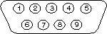
Many older PCs are equipped with two serial ports and one parallel port. Although these two types of ports are used for communicating with external devices, they work in different ways.
A parallel port sends and receives data eight bits at a time over 8 separate wires. This allows data to be transferred very quickly; however, the cable required is more bulky because of the number of individual wires it must contain. Parallel ports are typically used to connect a PC to a printer and are rarely used for much else. A serial port sends and receives data one bit at a time over one wire. While it takes eight times as long to transfer each byte of data this way, only a few wires are required. In fact, two-way (full duplex) communications is possible with only three separate wires – one to send, one to receive, and a common signal ground wire.
Bi-directional communications
The serial port on your PC is a full-duplex device meaning that it can send and receive data at the same time. In order to be able to do this, it uses separate lines for transmitting and receiving data. Some types of serial devices support only one-way communications and therefore use only two wires in the cable – the transmit line and the signal ground.
Communicating by bits
Once the start bit has been sent, the transmitter sends the actual data bits. There may either be 5, 6, 7, or 8 data bits, depending on the number you have selected. Both receiver and the transmitter must agree on the number of data bits, as well as the baud rate. Almost all devices transmit data using either 7 or 8 data bits.
Notice that when only 7 data bits are employed, you cannot send ASCII values greater than 127. Likewise, using 5 bits limits the highest possible value to 31. After the data has been transmitted, a stop bit is sent. A stop bit has a value of 1 – or a mark state – and it can be detected correctly even if the previous data bit also had a value of 1. This is accomplished by the stop bit’s duration. Stop bits can be 1, 1.5, or 2 bit periods in length.
The parity bit
Besides the synchronization provided by the use of start and stop bits, an additional bit called a parity bit may optionally be transmitted along with the data. A parity bit affords a small amount of error checking, to help detect data corruption that might occur during transmission. You can choose either even parity, odd parity, mark parity, space parity or none at all. When even or odd parity is being used, the number of marks (logical 1 bits) in each data byte is counted, and a single bit is transmitted following the data bits to indicate whether the number of 1 bits just sent is even or odd.
For example, when even parity is chosen, the parity bit is transmitted with a value of 0 if the number of preceding marks is an even number. For the binary value of 0110 0011 the parity bit would be 0. If even parity were in effect and the binary number 1101 0110 were sent, then the parity bit would be 1. Odd parity is just the opposite, and the parity bit is 0 when the number of mark bits in the preceding word is an odd number. Parity error checking is very rudimentary. While it will tell you if there is a single bit error in the character, it doesn’t show which bit was received in error. Also, if an even number of bits are in error then the parity bit would not reflect any error at all.
Mark parity means that the parity bit is always set to the mark signal condition and likewise space parity always sends the parity bit in the space signal condition. Since these two parity options serve no useful purpose whatsoever, they are almost never used.
RS-232C
RS-232 stands for Recommended Standard number 232 and C is the latest revision of the standard. The serial ports on most computers use a subset of the RS-232C standard. The full RS-232C standard specifies a 25-pin “D” connector of which 22 pins are used. Most of these pins are not needed for normal PC communications, and indeed, most new PCs are equipped with male D type connectors having only 9 pins.
DCE and DTE devices
Two terms you should be familiar with are DTE and DCE. DTE stands for Data Terminal Equipment, and DCE stands for Data Communications Equipment. These terms are used to indicate the pin-out for the connectors on a device and the direction of the signals on the pins. Your computer is a DTE device, while most other devices are usually DCE devices.
If you have trouble keeping the two straight then replace the term “DTE device” with “your PC” and the term “DCE device” with “remote device” in the following discussion.
The RS-232 standard states that DTE devices use a 25-pin male connector, and DCE devices use a 25-pin female connector. You can therefore connect a DTE device to a DCE using a straight pin-for-pin connection. However, to connect two like devices, you must instead use a null modem cable. Null modem cables cross the transmit and receive lines in the cable, and are discussed later in this article. The listing below shows the connections and signal directions for both 25 and 9-pin connectors.
The TD (transmit data) wire is the one through which data from a DTE device is transmitted to a DCE device. This name can be deceiving, because this wire is used by a DCE device to receive its data. The TD line is kept in a mark condition by the DTE device when it is idle. The RD (receive data) wire is the one on which data is received by a DTE device, and the DCE device keeps this line in a mark condition when idle.
RTS stands for Request To Send. This line and the CTS line are used when “hardware flow control” is enabled in both the DTE and DCE devices. The DTE device puts this line in a mark condition to tell the remote device that it is ready and able to receive data. If the DTE device is not able to receive data (typically because its receive buffer is almost full), it will put this line in the space condition as a signal to the DCE to stop sending data. When the DTE device is ready to receive more data (that is, after data has been removed from its receive buffer), it will place this line back in the mark condition. The complement of the RTS wire is CTS, which stands for Clear To Send. The DCE device puts this line in a mark condition to tell the DTE device that it is ready to receive the data. Likewise, if the DCE device is unable to receive data, it will place this line in the space condition. Together, these two lines make up what is called RTS/CTS or “hardware” flow control. WinWedge supports this type of flow control, as well as Xon/XOff or “software” flow control. Software flow control uses special control characters transmitted from one device to another to tell the other device to stop or start sending data. With software flow control the RTS and CTS lines are not normally used.
DTR stands for Data Terminal Ready. Its intended function is very similar to the RTS line. DSR (Data Set Ready) is the companion to DTR in the same way that CTS is to RTS. Some serial devices use DTR and DSR as signals to simply confirm that a device is connected and is turned on. WinWedge sets DTR to the mark state when the serial port is opened and leaves it in that state until the port is closed. The DTR and DSR lines were originally designed to provide an alternate method of hardware handshaking. It would be pointless to use both RTS/CTS and DTR/DSR for flow control signals at the same time. Because of this, DTR and DSR are rarely used for flow control.
CD stands for Carrier Detect. Carrier Detect is used by a modem to signal that it has made a connection with another modem, or has detected a carrier tone.
The last remaining line is RI or Ring Indicator. A modem toggles the state of this line when an incoming call rings your phone.
The Carrier Detect (CD) and the Ring Indicator (RI) lines are only available in connections to a modem. Because most modems transmit status information to a PC when either a carrier signal is detected (that is, when a connection is made to another modem) or when the line is ringing, these two lines are rarely used.
9 to 25 pin adapters
The following table shows the connections inside a standard 9 pin to 25 pin adapter.
Baud vs. bits per second
The baud unit is named after Jean Maurice Emile Baudot, who was an officer in the French Telegraph Service. He is credited with devising the first uniform-length 5-bit code for characters of the alphabet in the late 19th century. What baud really refers to is modulation rate or the number of times per second that a line changes state. This is not always the same as bits per second (BPS). If you connect two serial devices together using direct cables then baud and BPS are in fact the same. Thus, if you are running at 19200 BPS, then the line is also changing states 19200 times per second. But when considering modems, this isn’t the case.
Because modems transfer signals over a telephone line, the baud rate is actually limited to a maximum of 2400 baud. This is a physical restriction of the lines provided by the phone company. The increased data throughput achieved with 9600 or higher baud modems is accomplished by using sophisticated phase modulation, and data compression techniques.
Cables, null modems, and gender changers
In a perfect world, all serial ports on every computer would be DTE devices with 25-pin male “D” connectors. All other devices would be DCE devices with 25-pin female connectors. This would allow you to use a cable in which each pin on one end of the cable is connected to the same pin on the other end. Unfortunately, we don’t live in a perfect world. Serial ports use both 9 and 25 pins, many devices can be configured as either DTE or DCE, and – as in the case of many data collection devices – may use completely non-standard or proprietary pin-outs. Because of this lack of standardization, special cables called null modem cables, gender changers and custom made cables are often required.
Cable lengths
The RS-232C standard imposes a cable length limit of 50 feet. You can usually ignore this “standard”, since a cable can be as long as 10000 feet at baud rates up to 19200 if you use a high quality, well shielded cable. The external environment has a large effect on lengths for unshielded cables. In electrically noisy environments, even very short cables can pick up stray signals. The following chart offers some reasonable guidelines for 24 gauge wire under typical conditions. You can greatly extend the cable length by using additional devices like optical isolators and signal boosters. Optical isolators use LEDs and Photo Diodes to isolate each line in a serial cable including the signal ground. Any electrical noise affects all lines in the optically isolated cable equally – including the signal ground line. This causes the voltages on the signal lines relative to the signal ground line to reflect the true voltage of the signal and thus canceling out the effect of any noise signals.
Gender changers
A problem you may encounter is having two connectors of the same gender that must be connected. You can purchase gender changers at any computer or office supply store for under $5.
Note: The parallel port on a PC uses a 25 pin female connector which sometimes causes confusion because it looks just like a serial port except that it has the wrong gender. Both 9 and 25 pin serial ports on a PC will always have a male connector.
Null modem cables and null modem adaptors
If you connect two DTE devices (or two DCE devices) using a straight RS232 cable, then the transmit line on each device will be connected to the transmit line on the other device and the receive lines will likewise be connected to each other. A Null Modem cable or Null Modem adapter simply crosses the receive and transmit lines so that transmit on one end is connected to receive on the other end and vice versa. In addition to transmit and receive, DTR & DSR, as well as RTS & CTS are also crossed in a Null modem connection.
Null modem adapters are available at most computer and office supply stores for under $5.
Synchronous and asynchronous communications
There are two basic types of serial communications, synchronous and asynchronous. With Synchronous communications, the two devices initially synchronize themselves to each other, and then continually send characters to stay in sync. Even when data is not really being sent, a constant flow of bits allows each device to know where the other is at any given time. That is, each character that is sent is either actual data or an idle character. Synchronous communications allows faster data transfer rates than asynchronous methods, because additional bits to mark the beginning and end of each data byte are not required. The serial ports on IBM-style PCs are asynchronous devices and therefore only support asynchronous serial communications.
Asynchronous means “no synchronization”, and thus does not require sending and receiving idle characters. However, the beginning and end of each byte of data must be identified by start and stop bits. The start bit indicates when the data byte is about to begin and the stop bit signals when it ends. The requirement to send these additional two bits causes asynchronous communications to be slightly slower than synchronous. However, it has the advantage that the processor does not have to deal with the additional idle characters.
An asynchronous line that is idle is identified with a value of 1, (also called a mark state). By using this value to indicate that no data is currently being sent, the devices are able to distinguish between an idle state and a disconnected line. When a character is about to be transmitted, a start bit is sent. A start bit has a value of 0, (also called a space state). Thus, when the line switches from a value of 1 to a value of 0, the receiver is alerted that a data character is about to come down the line.
This article is from TALtech, makers of WinWedge and other Windows software for collecting instrument data.
Last modified on November 3, 2026